This article explains how you can use a synchronous dual data center solution with Exasol.
Introduction
A synchronous dual data center solution has one cluster stretched across two separate sites (data centers).
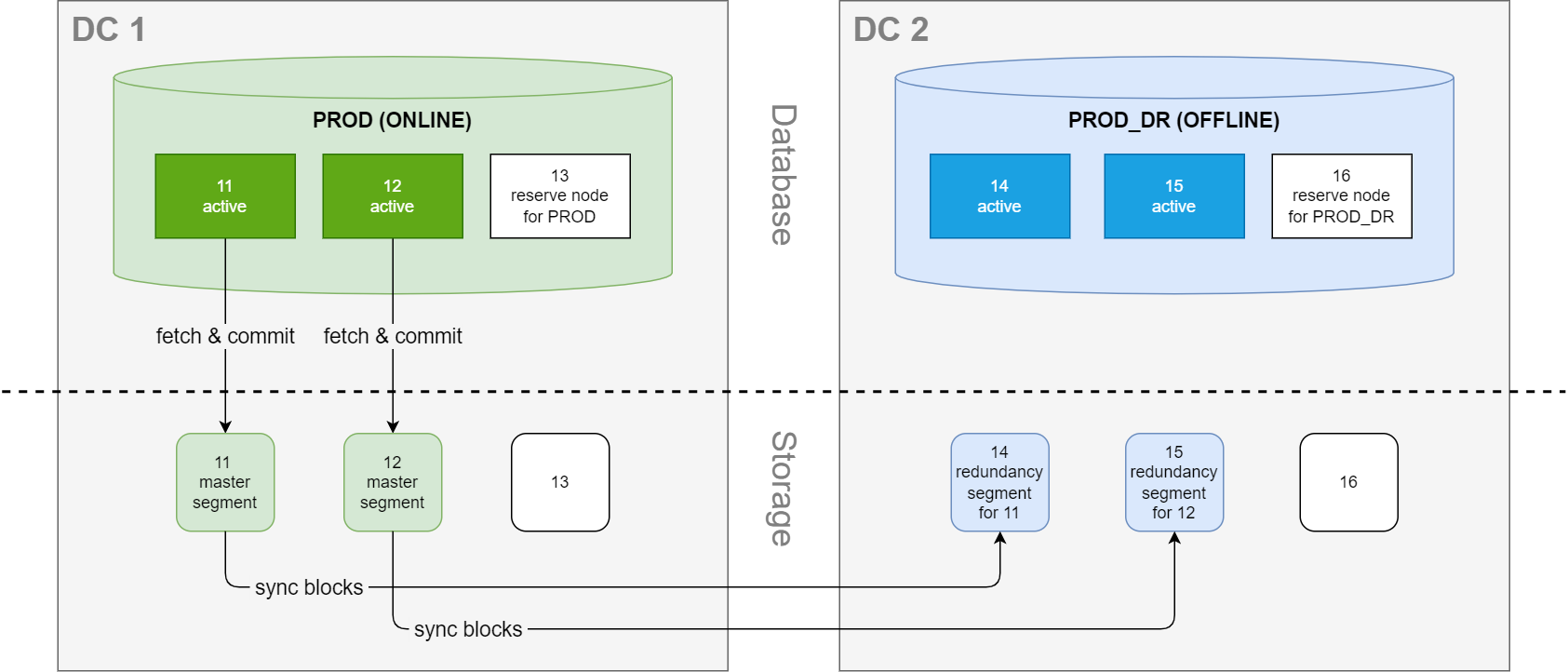
Each data center has a database instance with the exact same number of nodes. Because the instances share the same data volume, only one of the instances can be running at a time. The production database is normally running on the primary site, and data blocks in the master segments on the primary site are mirrored to redundancy segments on the secondary site.
This solution provides business continuity with minimum downtime in case of node failure or a complete outage on the primary site.
Network considerations
Because the communication between the data centers takes place on the storage layer, there is no risk of performance or syncing issues due to latency in the connection between the sites during normal operation. Performance will then only be limited by the network bandwidth between the nodes in the cluster. However, to avoid bottlenecks in the communication between the sites we recommend using either a dedicated network link or reserved bandwidth on a shared network, and to dimension the network bandwidth based on the peak aggregate workload, including all file transfers, backups, and failover traffic.
For more details, see How to dimension network bandwidth between data centers.
Examples
In the following examples, data center 1 (DC 1) is the main site and data center 2 (DC 2) is the secondary site. The production database instance PROD runs on the two active nodes n11 and n12, and has one reserve node, n13. The secondary database instance PROD_DR has two active nodes, n14 and n15, and one reserve node, n16. When the cluster is operating normally, the database is only running on the nodes in DC 1 while the nodes in DC 2 are offline.
In the storage layer, the active nodes in DC 1 operate on the corresponding local master segments, which are mirrored to redundancy segments in DC 2.
Site failure scenario
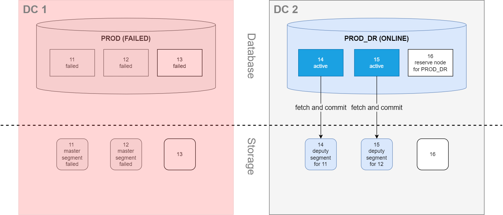
If DC 1 has an outage, PROD_DR is started on nodes n14 and n15 in DC 2 and operates on their corresponding local segments, which are now deputy segments for n11 and n12. This failover method causes zero data loss, and the database downtime is typically less than a minute.
Automatic failover on site failure is not provided by Exasol and must be set up separately.
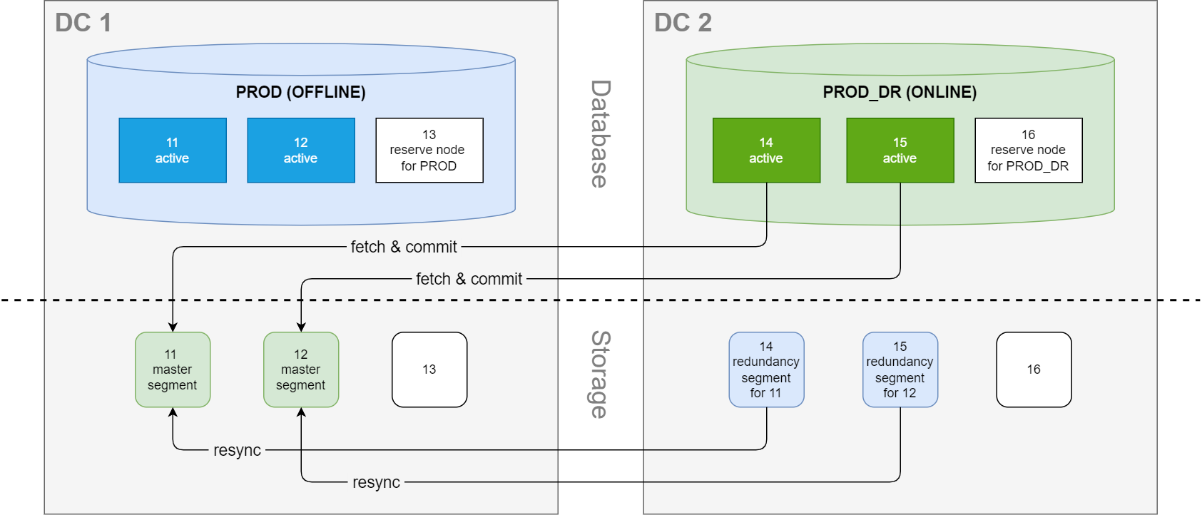
When DC 1 comes back online, PROD_DR operates on the n11 and n12 master segments in DC 1. However, these segments are now stale because of changes on the deputy segments in DC 2 during the outage. The segments are therefore resynced.
Node failure scenarios
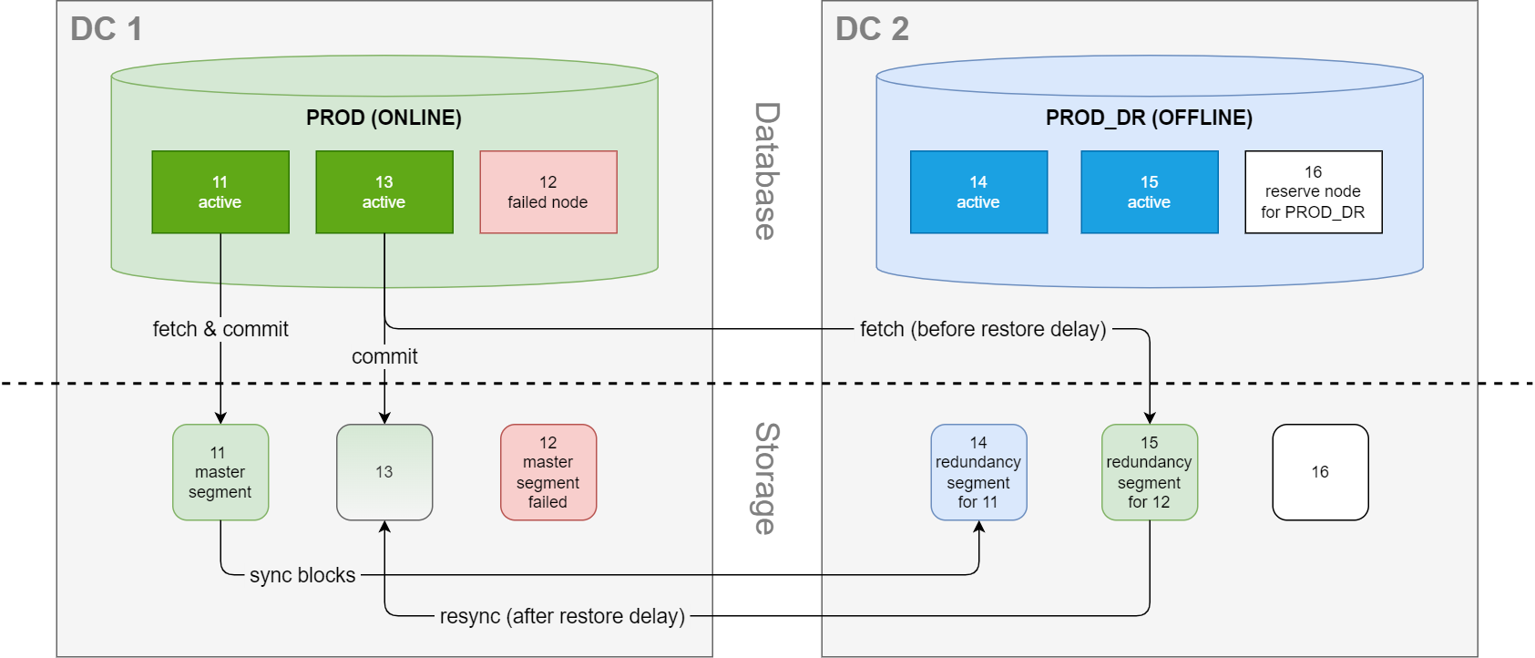
If one of the active nodes in DC 1 fails, the database is automatically restarted. The former reserve node n13 is then activated and immediately operates on the corresponding redundancy segment in DC 2. This is essentially the same behavior as in a normal hot standby
failover procedure, except that the redundancy segment is on a secondary site.
What happens next depends on whether the node comes back online within the restore delay threshold (transient failure) or not (persistent failure). The default restore delay threshold value is 10 minutes.
Transient node failure: segments on reactivated node are stale and resynced
If the failed node is back online within the restore delay threshold, copying data over the network is not needed. However, the master segment on DC 1 is now stale and must be resynced from the redundancy segment on DC 2 (copy-on-demand).
Persistent node failure - master segment is recreated
If the failed node is not back online within the restore delay threshold, the failure is considered to be persistent. The master segment on DC 1 is then recreated from the redundancy segment on DC 2.
This operation can be very time consuming, depending on the amount of data that must be transferred.
The instance on node n13 will continue to operate on the redundancy segment in DC 2 until the database is restarted.
Since the database is now operating across both sites, there is a risk of performance and syncing issues due to network latency. Restart the production database as soon as possible when the failure has been resolved.
How to dimension network bandwidth between data centers
The connection between the two data centers requires either a dedicated network link or reserved bandwidth on a shared network to avoid bottlenecks. Performance is influenced by network latency, disk I/O, and the shared/limited bandwidth, and can also be impacted by firewalls or encryption. Network saturation may also make cluster nodes unresponsive, threatening stability. To provide redundancy in case of a network outage, we recommend using an aggregated network.
The following section provides guidelines on how to dimension network bandwidth to minimize bottlenecks and avoid performance loss.
How to calculate the minimum required bandwidth
Example:
Database commits only:
3 nodes × 4 disks per node × 200 MB/s per disk = 2,400 MB/s
If backups are running simultaneously, assuming each node backs up at 250 MB/s:
3 nodes × 250 MB/s = 750 MB/s additional base load
Total required bandwidth:
2,400 MB/s (commits) + 750 MB/s (backups) = 3,150 MB/s
Convert MB/s to Gbit/s:
3,150 MB/s / 125 MB/s (per Gbit/s) = 25.2 Gbit/s
Result:
For this example, provision at least 25 Gbit/s bandwidth to handle peak database and backup activity without bottlenecks.
Disk throughput is a theoretical maximum. Actual throughput depends on disk type (SSD, NVMe, HDD), IOPS, block size, encryption, controller features, size and frequency of database writes (small or large blocks), and the type of database queries being executed.
The example only takes peak write operations and backups into account. Be sure to include all regular and exceptional loads (application traffic, management tasks, etc.) in final network sizing.
Throughput reference table
The following table shows the approximate transfer times for transferring either 30 GB or 3 GB (numbers are randomly chosen) at maximum available throughput, not accounting for protocol or environmental overhead.
Actual transfer rates will typically be lower due to real-world factors.
|
Bandwidth |
Throughput |
Transfer time for 30 GB data |
Transfer time for 3 GB data |
|---|---|---|---|
|
1 Gbit/s |
125 MB/s |
~245.8 s (4.1 min) |
~24.6 s |
|
10 Gbit/s |
1,250 MB/s |
~24.6 s |
~2.5 s |
|
20 Gbit/s |
2,500 MB/s |
~12.3 s |
~1.2 s |
|
40 Gbit/s |
5,000 MB/s |
~6.1 s |
~0.6 s |
Recommendations
-
Match the bandwidth of the connection with the peak aggregate workload, including all file transfers, backups, and failover traffic (storage recovery).
-
Use higher bandwidth for high-performance clusters with simultaneous database writes and backups.
-
Always analyze actual production workloads and consider real-life testing to validate theoretical sizing.


